TL;DR - use a theodolite with measurement poles at each end and in the middle. No iphones, laser pens or bowling balls needed. Sometimes it comes down to having the right tools for the job.
I was going to suggest something similar... just put the bowling ball at one end and if you can see the whole thing at floor level at the other end, it's straight, else it's curved.
It seems to me that unless they went out of their way to make it 'straight' local craftsmen are going to use a level any time they set something like a floor or wall, and therefore the building will follow the curvature of the earth. Above they speak of linear accelerators and how they have to make sure to keep things straight, rather than level. I doubt they'd go to that effort for an airplane terminal.
I don't like his method of measuring the curvature distance.
I think it will be very difficult to align a local to the local tangent of the earth's surface. Over a distance of 700m, the earth's surface deviates by about 4cm. This means we would have to align our laser to within 50 microradians in order to accurately measure the deviation of the earth's surface.
Further more, his two beam system is setup using two lasers spaced about 4m apart requires even greater accuracy. Let's imagine system 1 is aligned to the local tangent at one end of the terminal (x = 0m), system 2 is aligned to the local tangent 4 m away at x = 4m, and heights of the two beams are measured at the opposite end of the terminal (x = 700 m). The height difference between these two beams will be about 1 micron. If we assume that the beams are large enough that there is no spread in beam size, then each beam is about 3 cm in diameter. This means we need to measure the beam height to better 0.003% accuracy relative to the beam size. I think this will be a very difficult measurement.
I think there is a way you could very accurately measure the relative angle between two beams in a larger interferometer and two lasers, but I'll have to think about how it would look...
Regardless, it's always fun to think about this small corrections to our expectations. To be honest, I was a little surprised to think about it, 4cm of deviation over 700m is actually a bit larger than I expected.
Your approach mirrors what mine would have been. If the curvature of the earth can be measured over 725 meters, then to me, it's inconsequential whether or not that is detectable within this man-made construct.
That isn't to impugn the question, or the method, but that I'm less interested in whether the architects adjusted each each to be 4cm higher than they would need to be or not. Even if the airport were built over the course of 5 meters, in which the curvature would be (effectively) undetectable, the airport itself, being man-made, may exhibit irregularities caused by human error, shifting ground, variable bedrock, etc.
Regardless, the article was fantastically fun to read, as was your post.
You don't need to align anything: Point a single laser down the hallway and measure the height of the beam above the floor at the ends and at the midpoint. If the hallway is straight, these will fit a line; if the hallway is level, they will not. You can surely measure the heights to an accuracy much better than 4cm, and that's all that matters.
One could also use the bowling ball to answer the level vs straight question. Ignoring such nuisances as friction, on a straight floor, a ball let loose would roll towards the center of the hall, and oscillate around it.
In practice, it may be possible to somewhat reliably measure a difference in deceleration rolling the ball towards an end of the hall vs towards its center.
And of course, if one also has a scale, the weight of the ball can be used to see whether the floor is level.
> And of course, if one also has a scale, the weight of the ball can be used to see whether the floor is level.
Can you elaborate on this? Why would the weight be different if non-level? Unless you're meaning that the center-of-mass of the ball would be ~2 centimeters further from the center-of-mass of the Earth and 1/r^2 means a decrease?
The article depicts the difference between "level" (consistent radius from Earth's center) vs "straight" (line tangent to surface).
A bowling ball rolled on a very long straight hall would (assuming nearly negligible resistance etc) actually accelerate toward the center, then slow down, reverse, and oscillate until it stopped in the middle (the lowest gravitational position) because relative to the curvature of the Earth a straight line is higher at the ends than at the center.
A bowling ball rolled on a very long level hall would keep going (until resistance or confused staff stopped it) because there would be no gravitational change.
Where the ball centered on would depend on how the hall was constructed. The low point could be anywhere, though it would likely be somewhere between the two endpoints.
It would only be at the center of the hall if that's where the floor were tangent with the Earth's circumference.
The 1/r2 one. Going even more esoteric, I guess, in an idealized world, one can measure the deformation of the bowling ball due to gravity, and check whether it changes across the hall.
"First get a long East-West terminal and see if we can roll a ball all the way to the end of the hallway. There shouldn’t be any Coriolis deflection in that case"
The author is confused. That statement would only be true on the Equator. In the northern hemisphere, the ball will always deflect to the right. If I put a pencil on a globe, I can intuitively understand why, sometimes for up to five minutes!
It's familiar because it's a not uncommon comment. Well, except that most such comments refer to the Verrazano-Narrows Bridge, which has a longer span than the Golden Gate. For examples:
It's not unique to the V-N Bridge. Here's a generic version in:
- a NASA report from 1978, Skylab EREP Investigations Summary, says "For example, the support towers on each side of a long suspension bridge are several centimeters further apart at the top than at the bottom because of the curvature of the Earth" http://books.google.com/books?id=MEYgAAAAIAAJ&q=%22bottom+be...
and two links for the same observation for the Humber Estuary Bridge in:
That said, for Golden Gate-specific comments, see:
- Ghost Hunter's Guide to the San Francisco Bay Area (2005) ("The engineering is so perfect that the towers are actually five inches further apart at the top than the base to account for the curvature of the Earth.") http://books.google.com/books?id=oD52WFx2mykC&pg=PA71&dq=gol...
- Practical Digital Wireless Signals (2010) ("As an example, for the Golden Gate Bridge at San Francisco the tops of the towers are further apart than the tower bases by about 9 cm due to the curvature of the Earth") - http://books.google.se/books?id=itG9Zwf7eHAC&pg=PA261&dq=%22... .
Therefore, do you really believe that you are the originator of that fact, and due special attribution?
books.google.com , which is also the domain name for all of those links. The searches were various combinations of "golden gate" "curvature of the earth" and a few other bridge names.
It looks like this blog made their own version instead of copying yours. Since you can't own the fact, and they're not using your picture, they didn't take anything copyrighted or trademarked by you. Maybe you could argue that the stick-figure diagram is copyrightable, but it seems like a stretch.
No it doesn't. Not at all, except insofar as that basic sketch is depicted in a zillion trigonometry textbooks and has been for well longer than you've been alive.
The basic idea is pretty obvious. People have been computing "astounding facts" attributable to the Earth's curvature for thousands of years. Golden Gate Bridge is a pretty obvious choice for computing the tangible spread of two apparently parallel towers: WTC towers were too close for a dramatic spread, and other than GGB there isn't any other pair of towers so universally known (at least to an American audience) which are identical and far enough apart for a spreading of inches. If I think about it long enough, I'll probably recall seeing the same computation & example in trigonometry class decades ago.
Just because you thought of it doesn't mean you're first - by a long shot.
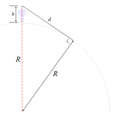
Oh, and your sketch is wrong. The two lines labeled "R" aren't the same length.
> Oh, and your sketch is wrong. The two lines labeled "R" aren't the same length.
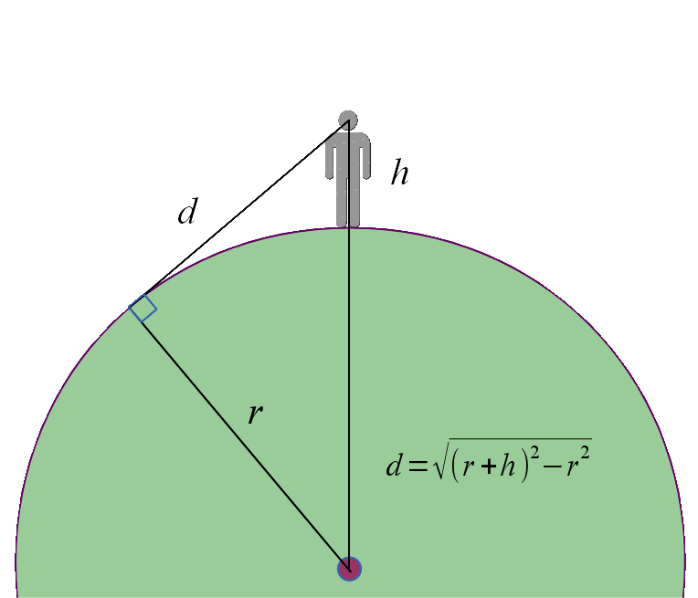
lutusp's diagram is the arachnoid one. His labels are correct, it's the datagenetics one that has apparently incorrect labeling. The dashed red line is not R in length, but R + h, which is not clearly indicated though the apparent intent. The dashed line should stop at the circle and change color or something to indicate a second line segment.
That said, you're correct. Ignoring the person another similar diagram is here:
http://en.wikipedia.org/wiki/Bedford_Level_experiment
TL;DR - use a theodolite with measurement poles at each end and in the middle. No iphones, laser pens or bowling balls needed. Sometimes it comes down to having the right tools for the job.